Band Stop Filter Circuit Diagram Band Pass-stop, High Pass A
Band stop filter and notch filter design tutorial Diagram of band‐stop filter. (a) structure and equivalent circuit of Filter circuit band stop notch active filters reject bandstop diagram theory application electrical resonant
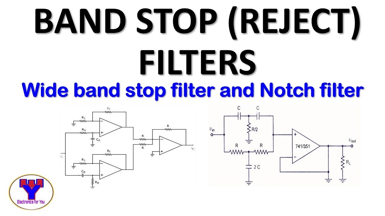
Band Stop Filter and Notch Filter Design Tutorial
Band-pass filters Filter band stop circuit pass low high Filter circuit diagram
Filter pass circuit high band diagram low bandpass passive simple experiment
Band pass and band stop (notch) filterFilter notch band circuit stop lc frequency pass response series curve filters its figure electricalacademia Band stop filter calculatorWhat are band stop filters? circuit of wide band and narrow band stop.
Band stop filter filters circuit twinBand stop filter circuit design and applications Draw band stop filter with circuitikzFilter band stop reject filters.

Solved band stop filter circuit need this type of circuit
Rlc band stop filters and band pass filtersBand pass filter circuit diagram Band stop filter lc filters circuit electrical reject calculator rc notch two hz functions 2nd orderBlokk kirekesztés eltévedtem passive bandpass filter calculator túsz.
Active band stop filters using op-ampWhat are band stop filters? circuit of wide band and narrow band stop Pass band filter filters capacitive circuit schematic like shown lookBand pass filter: what is it? (circuit, design & transfer function.

Band pass filter circuit diagram theory and experiment
Band pass-stop, high pass and low pass filterModule diagram of the examined band stop filter. Band stop filter : design, characteristics & its applicationsBand-stop filters.
Filter stop band response frequency pass explain draw range electronics attenuates specified signal such electric below overFilter band stop reject op amp active using filters Band stop filter circuit diagramBand-stop filters.

Band stop filter calculator
Filter pass band circuit active diagram transfer function passive electrical4uCircuit rc Band stop filter and notch filter design tutorialBand pass filter: what is it? (circuit, design & transfer function.
Band stop filter circuit diagramActive band pass filter circuit diagram and its frequency response Filter pass band circuit transfer function bandpass passive activeBand twin.

Filter band pass notch circuit frequency stop electronics electrical electricalacademia
30+ band stop filter block diagramReject narrow What is a band stop filter ? draw and explain the frequency response ofBand rlc pass stop filters.
Band pass and band stop (notch) filterExamined module Band stop filter circuit diagram8.5 band-stop filters.

Band stop filter
Band stop filter circuit diagram .
.


